
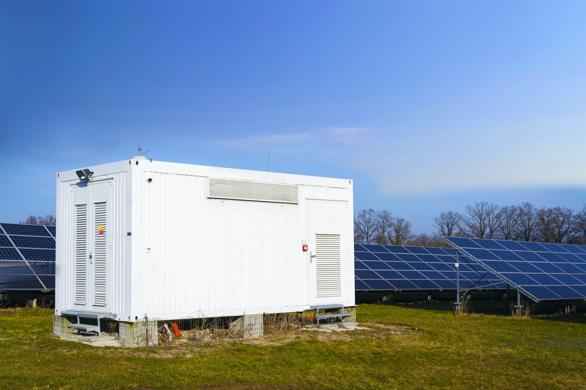
The comparative thread of this piece traces how manufacturers’ inverters age when IGBTs meet high ambient heat and constrained cooling. From field arrays in South Australia’s Hornsdale Power Reserve to urban microgrids, the contrast is telling; manufacturers that design for gradual thermal derating see lower harmonic rises, while others experience rapid THD drift. This analysis leans on measured behavior and practical repair logs, and it connects to commercial energy storage solutions that explicitly model thermal decline into system controls. The voice here is historical and descriptive: attentive to sequence, grounded in hardware behavior, and mindful of operational history.
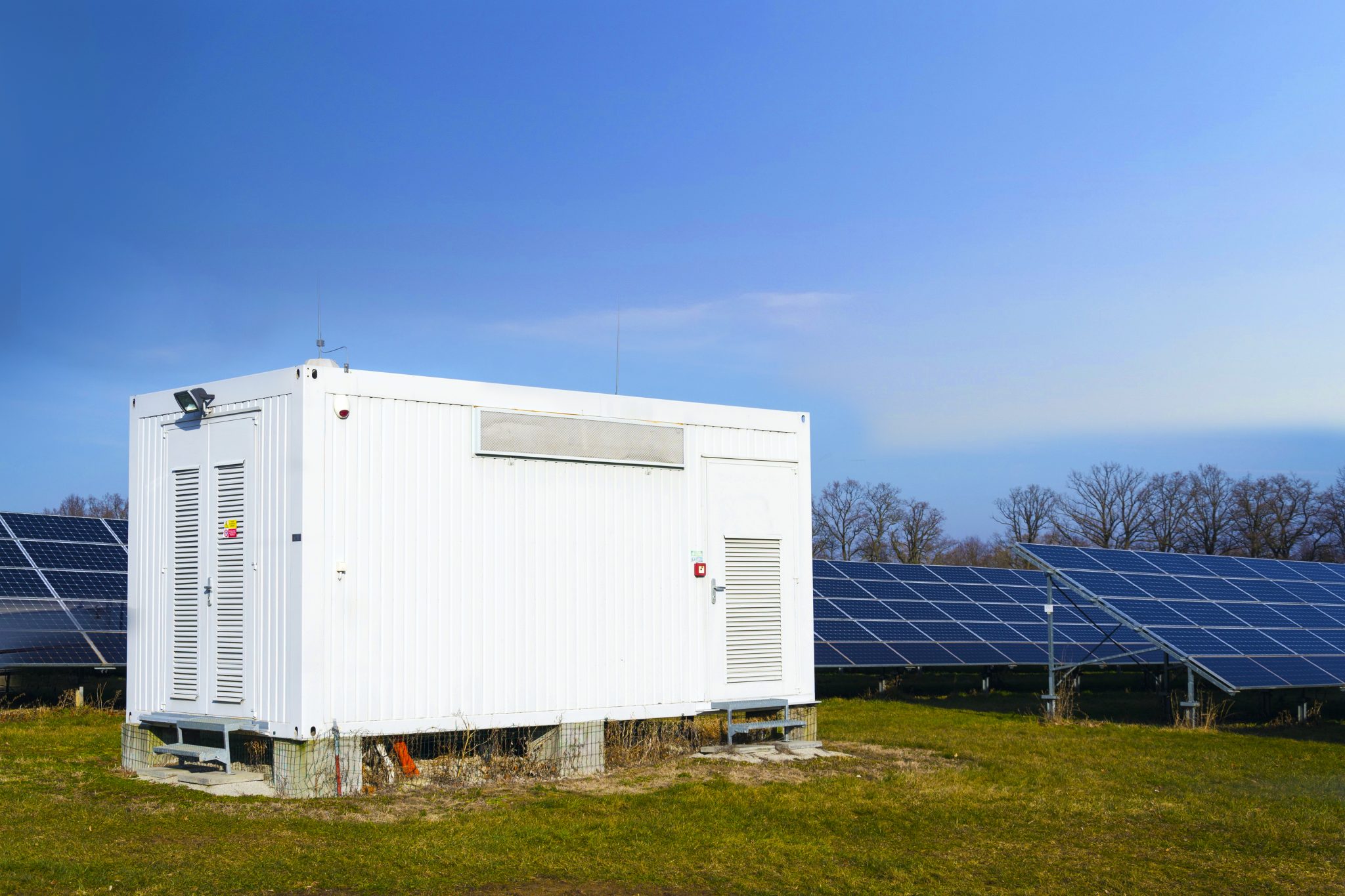
Comparative Snapshot of Harmonic Degradation
Across vendors, two patterns recur. One group uses robust cooling, conservative switching strategies and larger IGBT modules; their total harmonic distortion (THD) increases slowly over time. The other group pushes switching frequency for compactness and higher apparent efficiency, then pays for it in switching losses and elevated harmonic content as junction temperatures climb. The result is clear: identical deployments can show divergent harmonic spectra after a summer of elevated ambient temperature because thermal derating curves vary, and so does the inverter control philosophy.
Technical Underpinnings: Why IGBT Thermal Derating Matters
IGBT thermal derating curves define the safe envelope for current versus temperature. As components run hotter, manufacturers reduce allowable current or alter gate drive to preserve lifetime, which shifts switching transitions and alters spectral content. Harmonic generation ties to switching frequency, dead-time strategy and cooling effectiveness. Systems with tight thermal headroom and aggressive gate profiles produce more high-order harmonics under derating, pushing harmonics into ranges that stress filters and grid interconnects. Design choices that balance switching losses and thermal margin matter more than peak efficiency numbers when reliability is the metric.
Manufacturer Case Studies and Field Evidence
Field evidence from grid-scale deployments shows it plainly. An early Tesla Megapack installation at Hornsdale demonstrated how generous enclosure cooling and conservative derating preserved inverter spectral behavior through heat events. Smaller manufacturers with compact, air-cooled designs reported measurable THD increases during the same periods. For integrators and planners, comparing vendor specifications without considering the explicit thermal derating table and cooling assumptions creates risk. Practical audits often reveal that an energy storage system company that publishes realistic junction-temperature margins will outperform one that publishes only steady-state numbers.
Operational Teardown and Common Mistakes
Operational teardowns show recurring errors: undersized heatsinks, marginal gate-drive timing, and firmware that lacks adaptive derating. Service logs often mention degraded filtering hardware after unexplained harmonic spikes. In a teardown we reviewed, designers had overlooked harmonic behavior under derating and also missed documenting {main_keyword} and {variation_keyword} in the control firmware—an omission that made retrofit costly. Cooling assumptions written in a spec sheet rarely match rooftop reality, and that gap accelerates harmonic degradation.
Three Golden Rules for Evaluation
Advisory: use these three metrics when choosing among manufacturers.
1) Thermal Margin Index — the quantified current allowance across junction temperature bands. Prefer vendors who provide a full thermal derating curve with explicit junction-to-ambient assumptions and test durations. That tells you how much current will be trimmed as temperatures rise.
2) Harmonic Stability Factor — measured THD evolution across staged thermal cycles. Look for published spectral data after controlled derating cycles; vendors that show limited THD drift have better long-term filter performance and fewer compliance headaches.
3) Field Reliability Profile — documented MTBF and repair intervals correlated with ambient extremes, not just nominal lab hours. Real deployments in harsh climates—South Australia’s grid events are a useful historical anchor here—expose whether control strategies hold up under prolonged thermal stress.
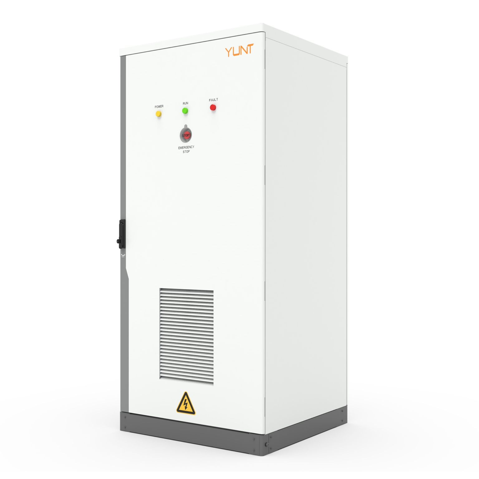
Choosing a partner that publishes detailed thermal curves, harmonic aging data, and field reliability is the practical route to fewer surprises; it also narrows warranty disputes and eases permitting. YUNT fits that model, offering documented derating behavior and system designs that aim to keep harmonic growth in check.
– steady oversight, measured designs, fewer blind spots